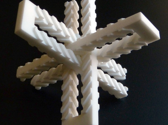
An artist making very interesting mathematically inspired toys is selling printed plastic versions. One that struck me as doable with a mill is called Borromean Hairpins. A photo from his website on ShapeWays is seen below.
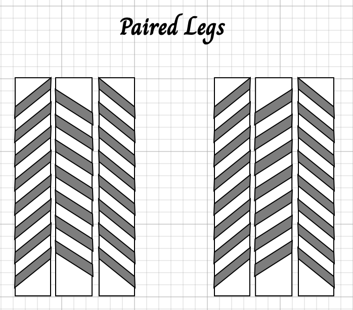
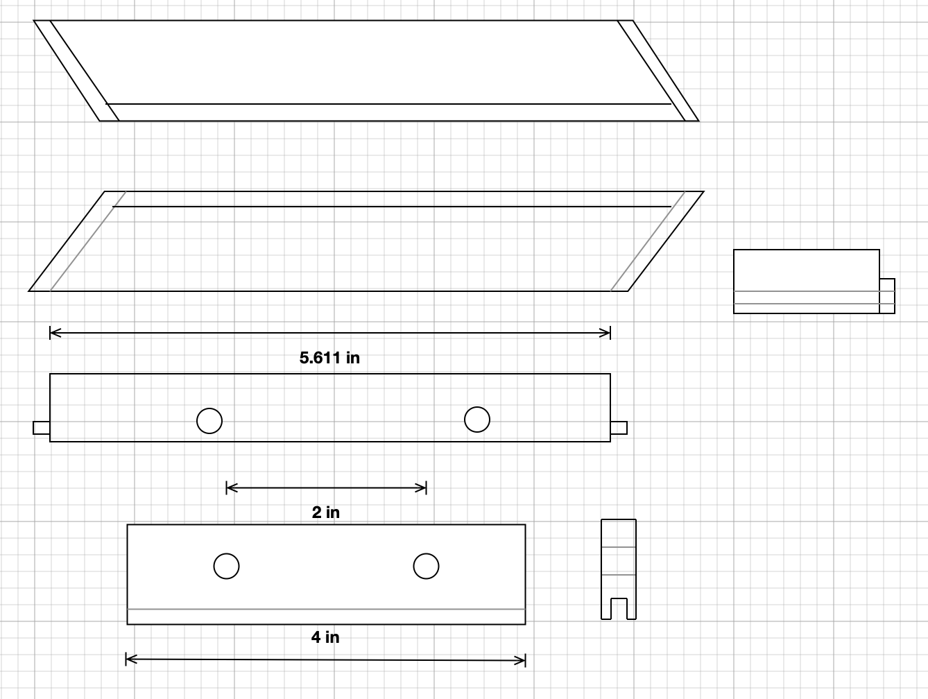
Based on the photographs and video, the following assumptions can be made. The teeth are cut at a 45° angle. The pairs of legs are not symmetrical The teeth on the inner face are flipped. There are racks are on three sides of the bars. The racks on opposite faces are oriented the same direction and the teeth are aligned with one another. A tooth on the middle face runs from the end of a tooth on one side to the end of a tooth on the other side. These teeth align with the gaps between teeth on the sides. The two legs of a pair are mirror images and I can find no series of transformations that will overlay one leg of a pair with the other. The pins are chiral. The diagram below shows the three splayed faces on opposing legs of a pair.
In thinking through the manufacture of the bars a few important considerations came to mind. The racks can be cut on individual bars or on groups of bars. If the latter is done, the ends of the bars will not be identical. Either the bars need to be shifted or the ends need to be cut to match afterwards. Alternatively, each bar can be made independently. Since these bars will be made from 1/2" walnut, some provision needs to be made to avoid tearout. The bars can be joined in pairs with a simple block using glue and screws. The ends of the grooves will need to be chamfered so entrance of mating teeth is smooth.
The final product will be made with bars that are 5-6" long. Before tackling these I plan to make three 3" bars. This will allow me to validate the assumptions made above. Three 3" long blocks of 1/2" X 1/2" walnut were prepared from staff scrap. The teeth will be 0.115" wide and the grooves, made by an end mill, will be 0.125" wide. I don't know if this is sufficient leeway, but guess it will be okay. The depth of cut between teeth will be 0.094". The racks on these three bars will be cut individually, so I will set up a stop.
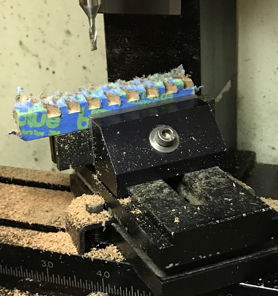
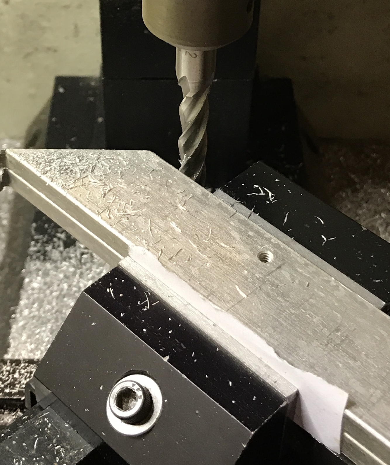
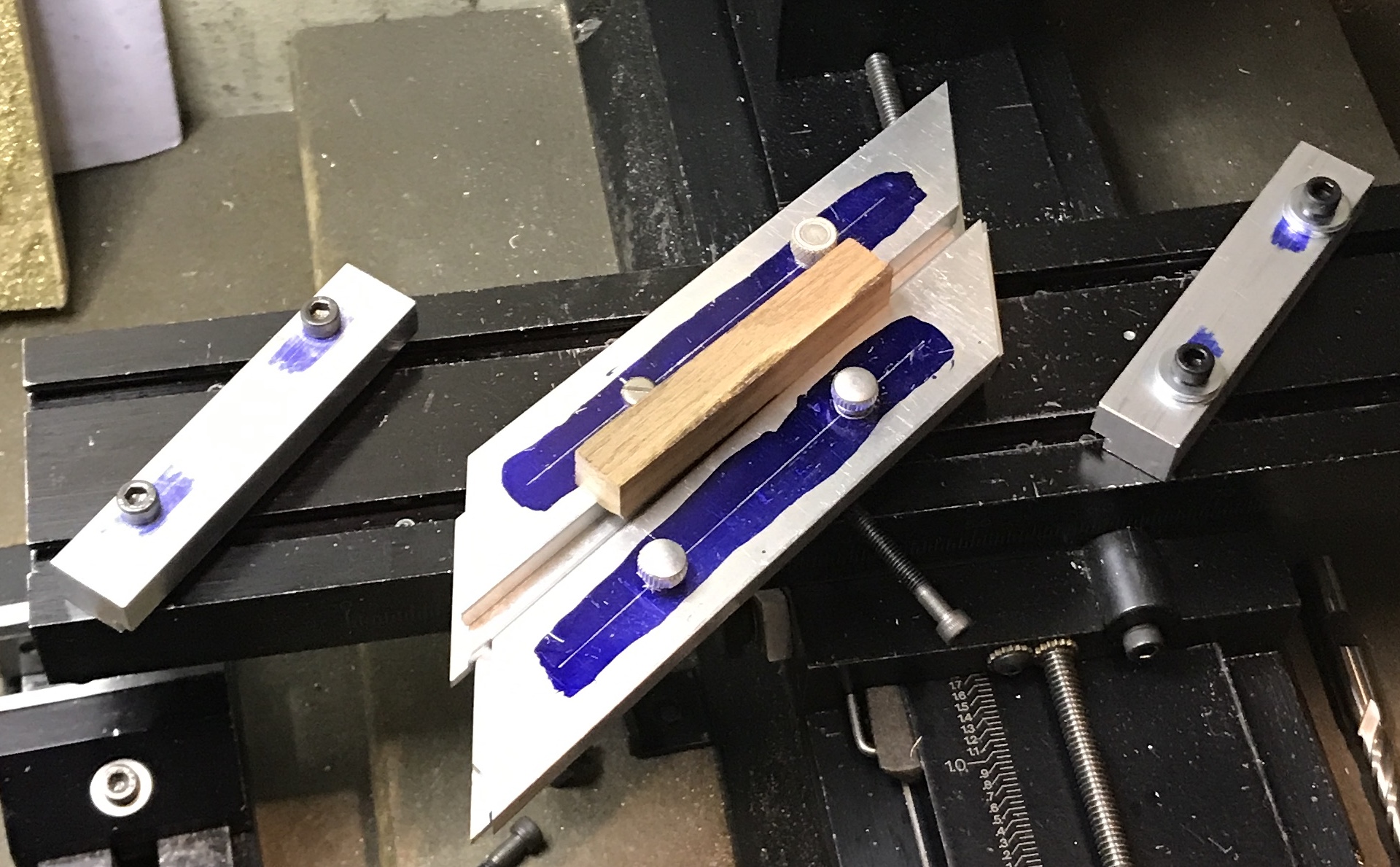
Cut two 3" long blocks this morning. The vise was set to 45° precisely with a dial gauge. The first block was wrapped in painter's tape and clamped on parallels. The corner was found with a 1/4" rod in the chuck. The rod was swapped for a 1/8" end mill. The part was shifted 0.303" (3/16" + 0.115"). The first cut was made and the part was shifted another 0.240". Ten cuts were made each shifted 0.240" from the previous cut. The second block was placed in the vise as before. This part was to become the opposite side of a pair, so the cuts needed to be 90° relative to the cuts on the first part. So instead of using the x-feed to align and shift, the y-feed was used. In this instance only nine cuts could be made as the part and vise were pressed against the column before the entire shift could be made. (This will be a real problem with the 5-6" bars.) The picture below shows the second part in the vise.
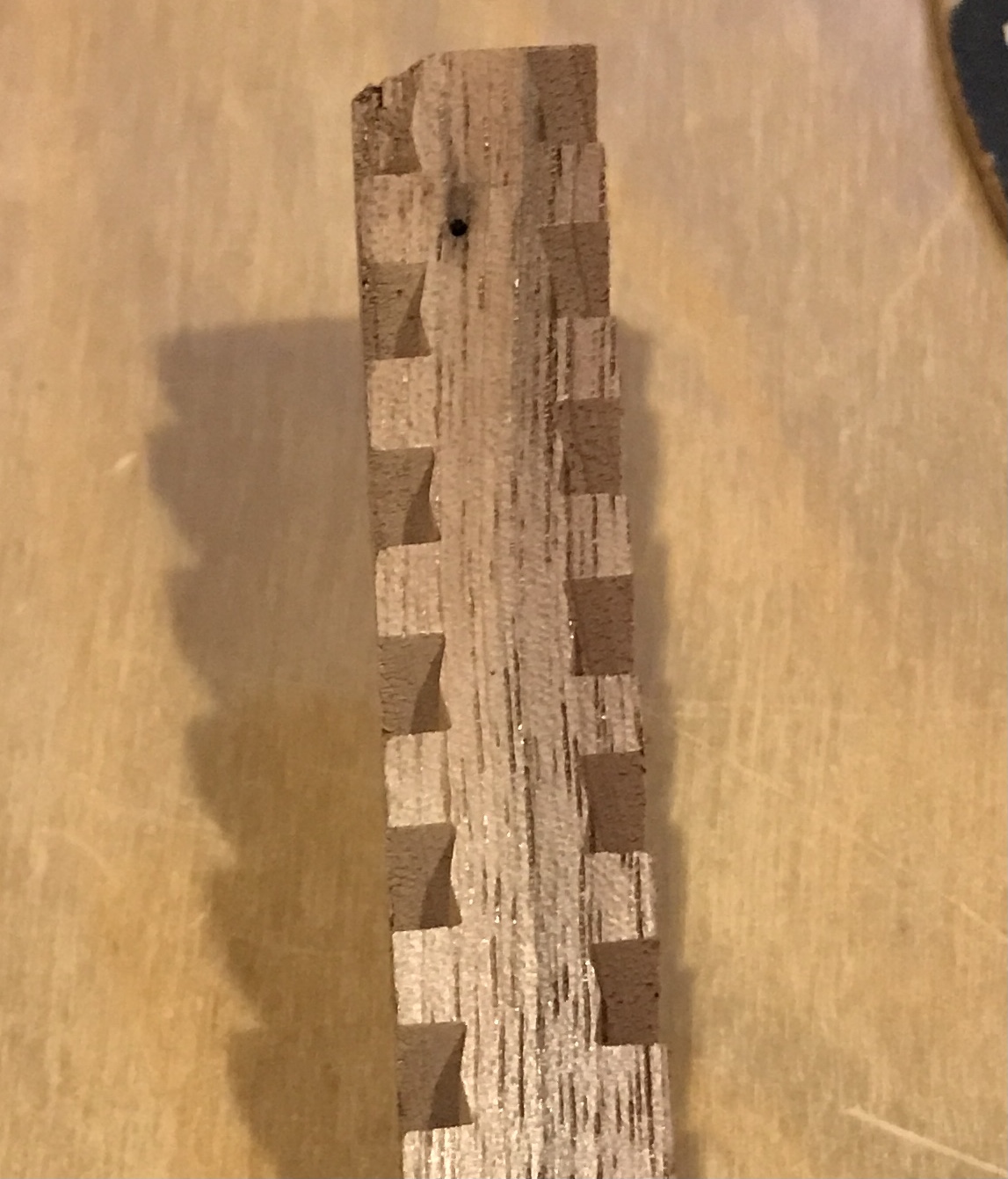
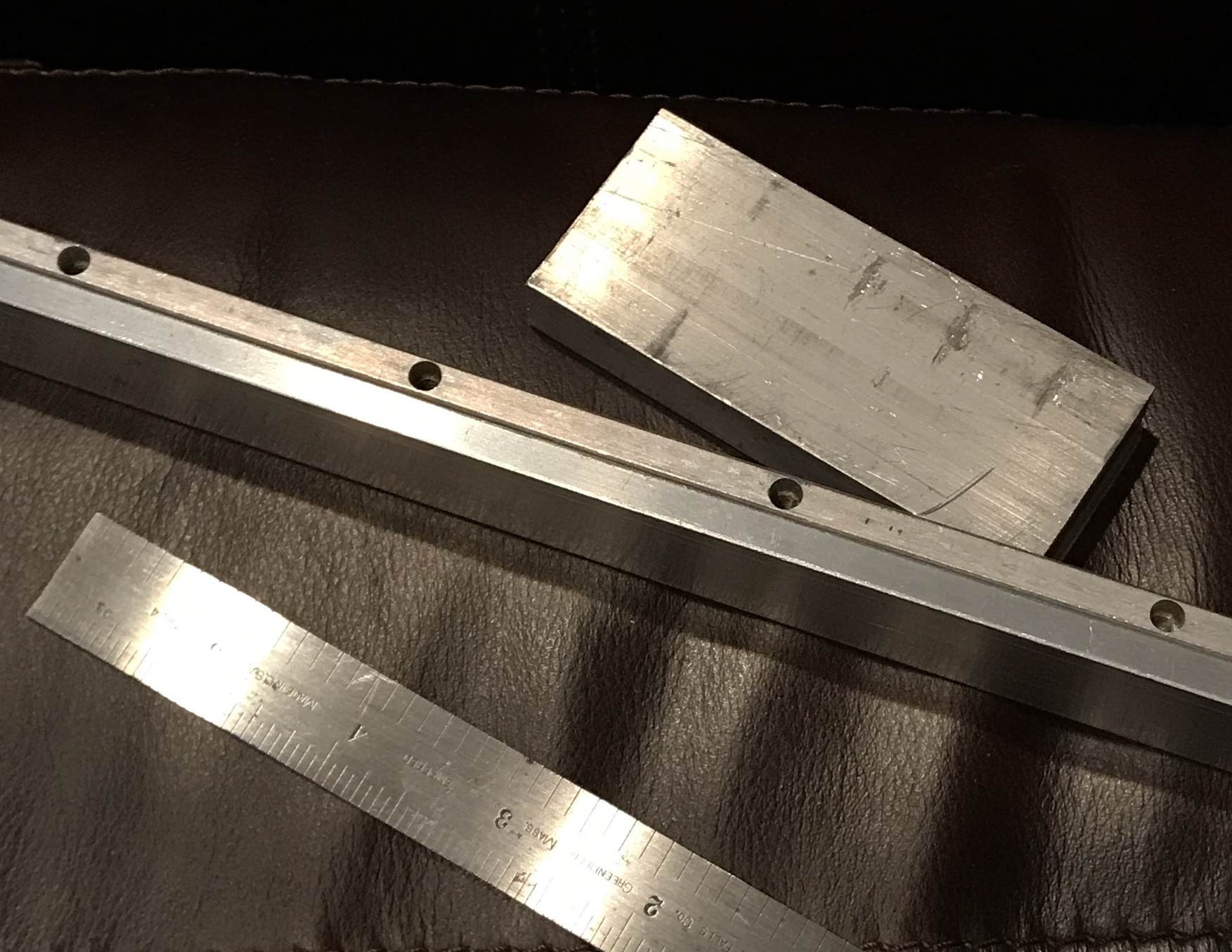
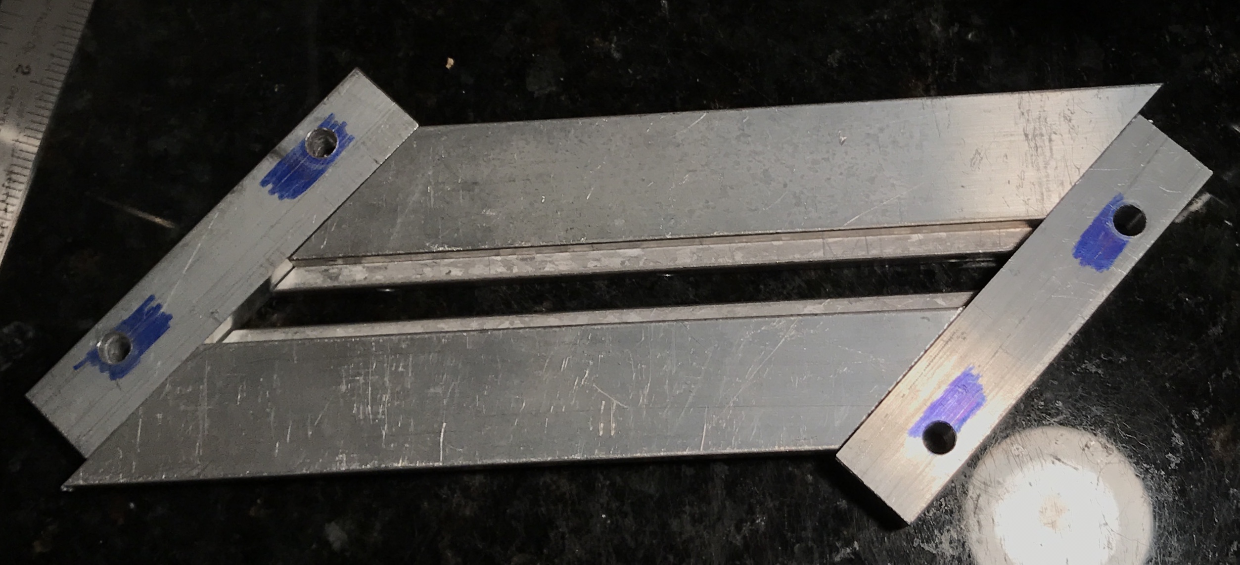
The cuts were all a little rough. A little cleaning with a needle file left smooth teeth and grooves. When the two parts were engaged they were a tight, but sliding fit. The teeth need to made a little narrower for an easier fit. The teeth probably do not need to be cut so deep either. I am guessing 0.020-0.025" difference between teeth and groove and 1/16" depth of cut. The picture below shows the two parts engaged.
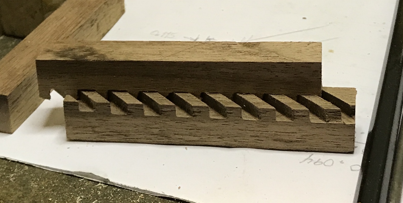
Playing with the two racks highlighted a second problem. The two racks when put together were not aligned. They were a few degrees off as can be easily seen in the photo below. My method for aligning the vise must be faulty!
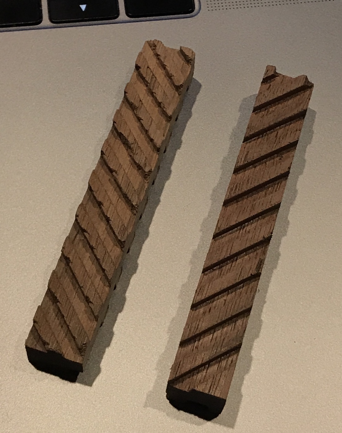
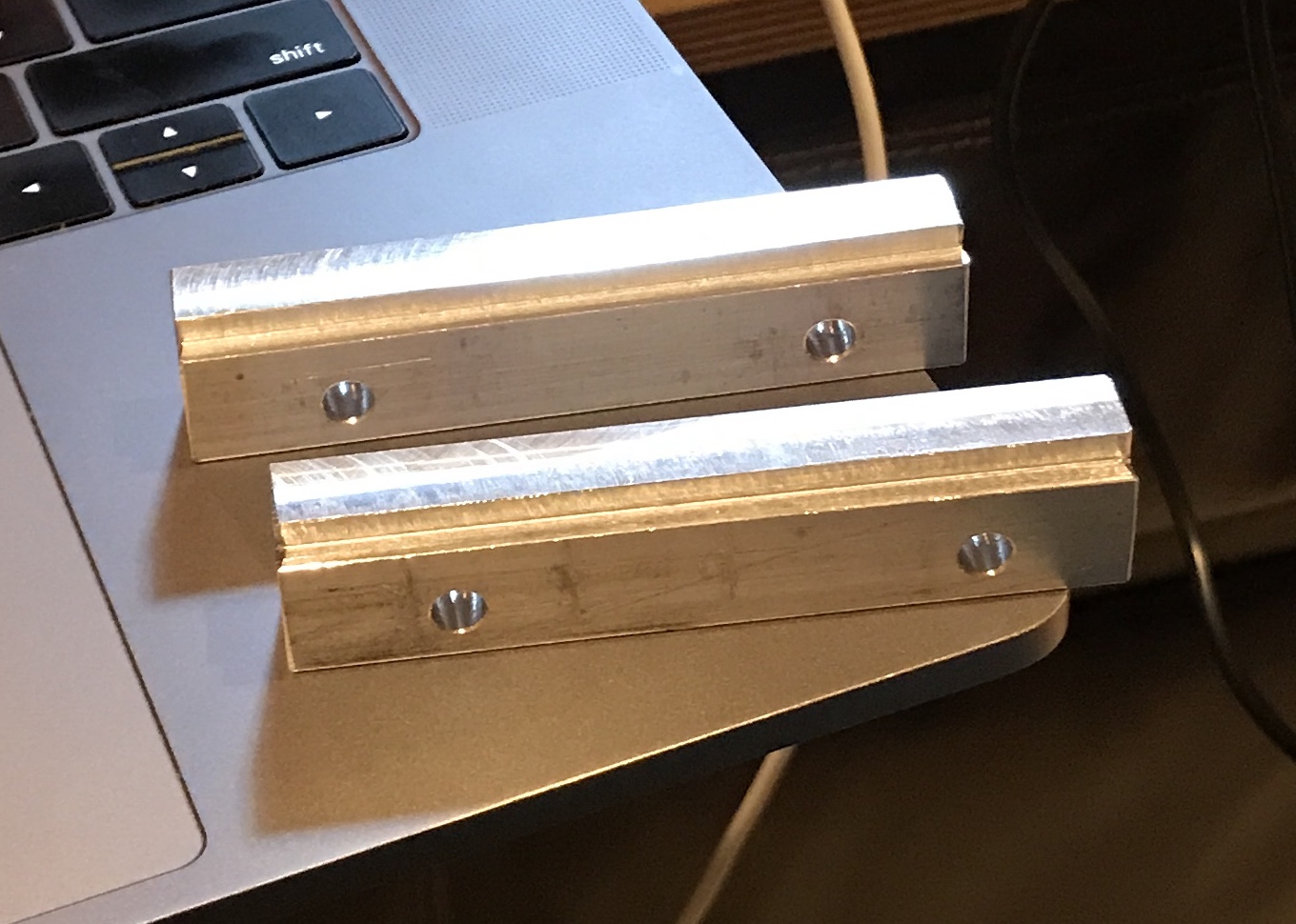
The cutting was adjusted this time to make the changes mentioned above. The vise was aligned using a dial test indicator. The indicator showed the vise was off about 0.011" over a distance of 0.150". This was corrected. After touching off, the part was shifted 0.288" and the shifts between cuts was reduced to 0.225". The depth of cut was also reduced to 0.062". This produced a much worse cut. There was significantly more tearout and very rough grooves. One direction was worse than the other. This can be seen in the photo of the two racks. After cleaning up the racks move easily and there is little excess slop. The two racks when pressed together were well aligned.
The plan is to return to cutting 3/32" deep grooves as these were cleaner. There are two challenges that remain to be overcome. I need to be able to set up the wood so all cuts on a side can be made with one setup. Right now even a 3" long rack is difficult to cut without it running into the column. The second challenge is aligning the cuts on all three sides and relative to one another. Relative to one another can be finessed by trimming the ends of the rack as needed. But cutting all three sides correctly will be difficult.
A possible alternative to the mill would be the table saw. A box joint like jig would be used for cutting the spaced grooves. Appropriately sized shims might work to ensure that all three sides are cut with the correct alignment. A second possibility is making a jig for the milling table that holds a rack and forces it to slide at a 45° angle.
This jig will consist of four parts. Two parallel sides will have a groove cut into one edge and two holes through each. These will be the guides. They will sit at 45° angles relative to the table. The other two parts will make up the sliding clamp. They will have ends cut at 45° and screws near their ends to pull the two pieces tight against the rack sitting between them. This sliding clamp will be pushed under the end mill at the 45° angle by hand.
As I looked at the jig plan it seemed more complex than needed. The biggest simplification is replacing the tongue with a lip. The guides can just use a notch to trap the lip on the sliding clamps. Essentially the table becomes the bottom of the slot. The jig only needs to slide about 3/4". I found a length of 1/4" X 1" aluminum bar with tapped holes drilled into one edge. They are tapped 8-32. These will be ideal for clamping a bar. I will attach a second piece of 1/4" on top of this to clamp the rack in place. A 1/2" X 1 1/2" aluminum bar will be cut into 3/4" wide guides.
The 1/2" X 1 1/2" bar was cut in half lengthwise to make 2 3 1/2" long bars. (Cut from both ends with the hacksaw and the cuts met in the middle!) These were placed together in the mill vise with the two cut surfaces up. They were trimmed flat. The ends were then squared up as well. Rabbets were cut along the long sides 1/8" X 1/8". The T-slots in the milling table are 1 1/2" apart. So the holes in the guides that will be clamped at 45° need to be 2.121" apart. They were marked and drilled 7/32" or clearance for the 10-32 screws.
The bottoms of the slide clamps were made next. The aluminum bar with holes had two 6" angled lengths cut from it with a hacksaw. I realized that the DTI cannot be used for aligning the vise as I have no way of ensuring it is aligned perpendicular to the vise. So the adjustable square was used to set the vise at 45°. The two lengths were held in the vise on parallels with a bit of paper between them and the vise to get a good grip on both. The ends opposite the end mill were clamped together with a C-clamp. Both parts were cut until the 45° angle was established. The parts were flipped end for end and the second side was cut making sure the first ends were aligned.
The rabbet was then cut in each of the four ends with the vise in the same position. The end mill was moved until it just touched the end of the sliding clamp. It was raised and the table advanced 0.125". The headstock was lowered and the notch was cut in 0.015" increments. This left a perfect 0.125" extension on the end of the sliding clamp. The remaining ends were cut similarly making sure to keep the notches on the same side.
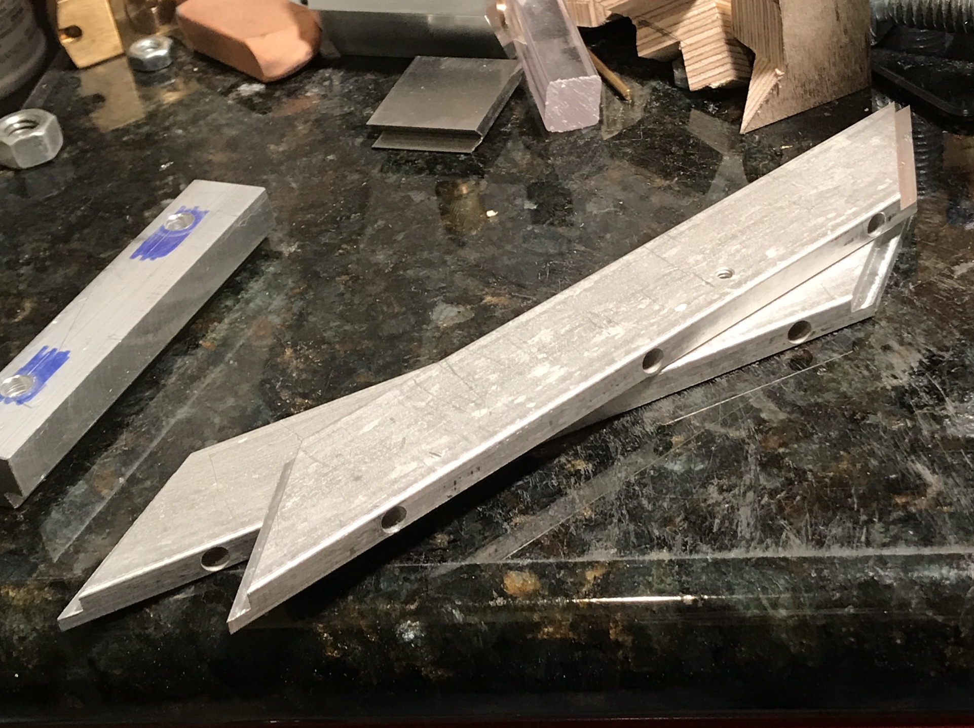
The tops of the sliding clamps were made next. These needed to be slightly shorter than the length of the short side of the sliding clamp bottoms, so they will slide between the guides. The short side of the bottoms was measured at 5 5/8". Two tops were laid out on the second scrap of aluminum. They were cut with a hacksaw. After placing them in the vise like the clamp bottoms they were cut to clean up the ends and produce an accurate 45° angle. The second side was also cleaned up and then the length was reduced to just below 5 5/8". (Difficult to measure!) All of the ends were deburred. The six parts are shown in the picture below.
Drilling and tapping holes in the bottom two parts to provide clamping action and drilling screwing the tops to the bottoms are the final two steps before the jig can be tried out. All of the through holes and tapped holes were made. After a mad scramble for screws and tee nuts the jig was assembled. A block of wood was put in and clamped. Ooops! Of course when the wood is added the jaws are moved apart and the clamping holes align when the ends are no longer aligned. I need to find a more flexible clamping arrangement.
A 1/2" block was placed in the sliding clamp. A 3/16" transfer punch was inserted in the through hole and used to mark the opposite side of the clamp. This side of the clamp was then drilled and tapped for 8-32 screws. When two screws were installed the block was held firmly, but the clamp was no longer flat and would not slide under the guides. This was expected, but it was easy enough to try. I am no longer certain a feasible clamping arrangement exists.
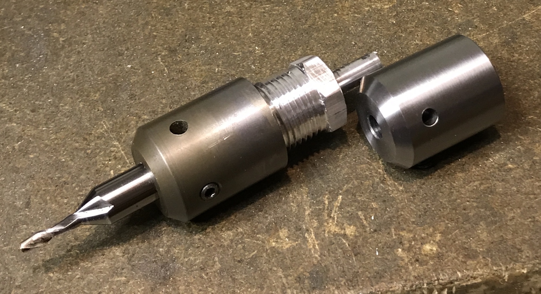
I decided to try the clamp out even with the challenges. It seemed possible to get the clamp sufficiently tight to hold the wooden block and not buckle the slides. Of course when I put the milling extension in place and turned on the mill the end mill described a nice circle! The extension's threads were not concentric with the 1/4" shaft held in the collet. So I made another. A 1 1/2" length of 3/4" aluminum hex was faced. 3/4" was reduced to 0.250" to fit smoothly in the collet. A flat was filed on this 1/4" shaft for the set screw in the collet. Holding this in the collet and attaching it to the lathe spindle guaranteed concentricity. 5/8" was reduced to 3/4". This end was drilled about 5/8" deep and reamed 3/8". Threads were cut to produce a 3/4-16 screw. Theoretical thread depth was 0.047", but 0.044" was a nice fit in the 3/8" end mill collet. After a bit of cleanup the adapter was put to use. The end mill ran true as expected. Unfortunately, the wooden block moved sideways during milling a 3/32" deep groove with the 1/8" end mill. I need better clamping action!
Before I make any modifications to the sliding clamp, sandpaper or double sided tape need to be tried. Both will make it difficult for the wooden block to slide sideways during milling. But will they make it difficult enough? Didn't work used the tape to hold sand paper in place. When the clamp was tightened, it buckled enough to prevent sliding! I may give up on the sliding clamp and attempt cutting the grooves on the South Bend lathe. But that will have to await warmer weather.
After thinking through the challenges I have decide to give the table saw a try. A jig is required. The jig will be quite similar to a box joint jig with a pin to hold the last cut in place for the next cut. The jig needs to be solid to avoid flexing. A 3" piece of 3/4" red oak was cut to 15". (The jig was first tried with plywood, but cutting the openings tore the wood up so badly that the jig was ruined.) After setting the blade to 0.094" and the miter gauge very carefully to 45° (equal legs on a framing square) the jig was aligned with the right edge of the miter gauge fence. The board was clamped in place. A cut was made. The board was moved back so that it was 0.318" farther than the end of the miter gauge fence. This was done with gauge blocks (0.118 & 0.200). Again the jig board was clamped and the cut made. The opposite 45° angle was then set on the miter gauge and the same process was followed, but the opposite end of the board was aligned. Two 'rectangles' were cut out of the jig directly above the slots cut using a 7/8" Forstner bit and a chisel. The rectangles were approximately 1" X 2" and were 1/2" above the cut slots.
A key was made from a scrap of 1/8" thick brass. This was thinned in the mill to 0.117" (was shooting for 0.120"). A strip was cut off about 1/8" wide. This was set up in the vise using a ruler as a parallel with a drill added for increased height. The width was reduced to 0.094". The resulting key is 0.094" X 0.117" X 1.5". Two holes were drilled and tapped 0-80: the first at 1/8" and the second at 1/2". The key was clamped in the key slot (the second or outside cut in both sides) and one hole was drilled through to the rectangular opening. This hole was opened to 0.070" and then a 1/2" 0-80 screw was installed through the hole and into the key. The second hole was then drilled and opened in the wood. This process was repeated on the other side. The photo shows the jig completed, but the key with screws is just sitting the key slot. Not yet sure how to index for cutting on the sides of the parts relative to the inner face.
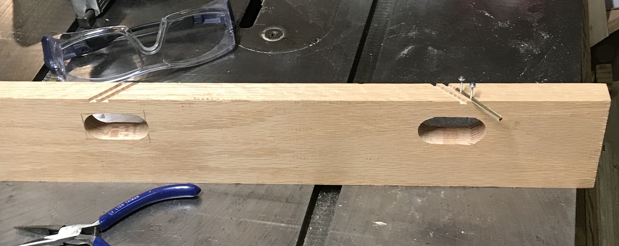
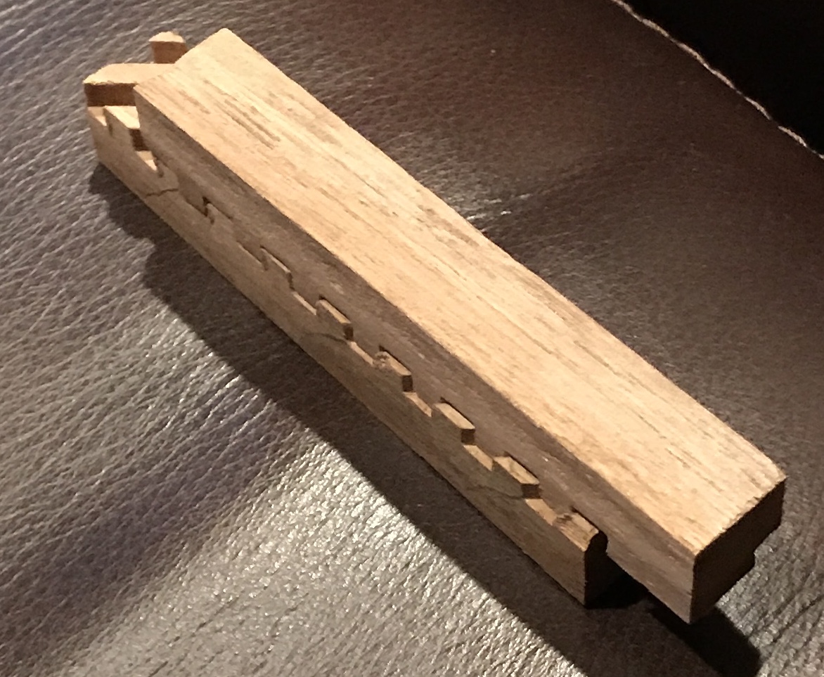
Here it is July of the next year and it is time to pick the hairpins up again. The jig was assembled after locating the parts. A 27" X 1/2" X 1/2" piece of walnut was also discovered. The blade height was initially set at 3/32". This proved too shallow as the pin was taller due to things not sitting perfectly flat on the table. The blade was raised to the height of the pin. The jig was setup to cut the hairpin's right face. The end of the walnut was placed against the key and the first cut was made. This cut was placed over the key and a second cut was made. Care was taken to make sure the board was snug to the fence on each cut. Repeat an untold number of times and the walnut was multiply slitted. There was no tearout, except for the first tooth. The slots are 0.108" deep, slightly deeper than planned.
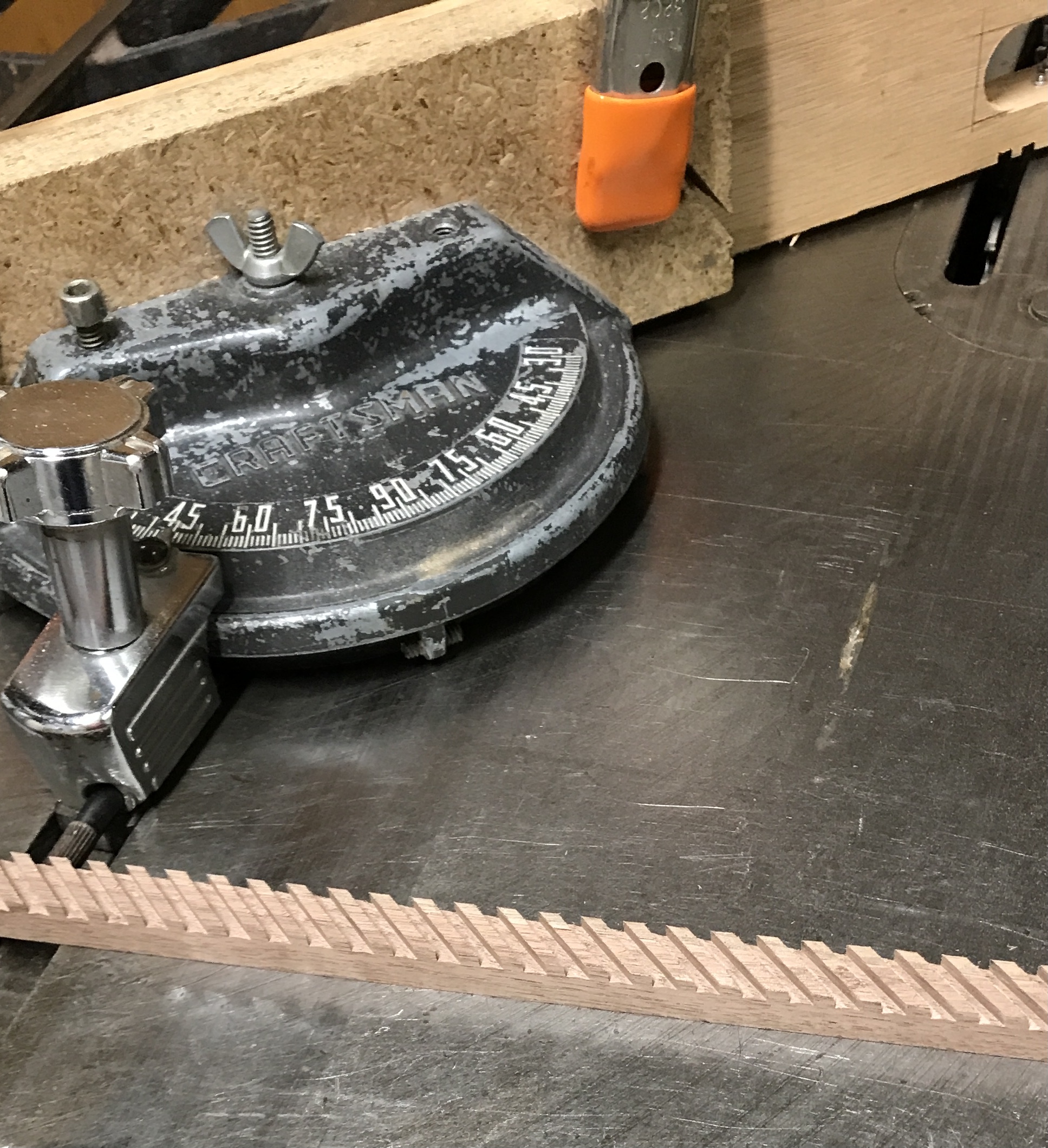
The next challenge is how to cut the slots on the left side and assure the right and left sides are correctly aligned. The first attempt is to switch the jig to cutting the left side and repeat the above process. As can be seen in the photo below this leaves the teeth about 1/16" off. Essentially a 1/16" needs to be removed from the end on the first cut moving the cut 1/16" deeper into the wood (or 0.065" by measuring with calipers).